
Fluid driver throughput (CCPS GPREH2 trim)
One of the flow limiting elements introduced in Excess inflow or outflow can be the fluid driver itself — the pump or compressor that establishes the maximum throughput available to the protected container at its relief pressure. The characteristics of the fluid driver are used to determine the volume of flow the fluid driver can provide to the container at its relief pressure.
Positive displacement pumps. For positive displacement pumps handling incompressible liquids, the volumetric flow of the pump is not expected to change significantly with an increase in pressure downstream. In a very few cases, the higher discharge pressure required for relief may stall the pump, in which case, consideration of the pump design may be used to limit the relief scenario. For many positive displacement pumps, the excess flow entering the container may vary with time or stroke. As a result, the instantaneous relief requirement may be greater than the average flow. For single-acting simplex pumps with little capacitance, the peak flow rate can be estimated by increasing the average flow rate by a factor of 3.14. This factor is less if there is significant capacitance in the system, for double acting pumps, or for multiplex pumps.
Many positive displacement pumps have internal relief valves to protect the pump from mechanical damage in the event of a blocked outlet. Some operators do not credit these internal relief valves as they are not necessarily inspected and maintained, and not usually code certified.
Centrifugal pumps. For centrifugal pumps handling incompressible liquids, the head required to deliver a fluid from the suction conditions to the downstream relief pressure is typically greater than the normal head; therefore, the pump characteristic curve can be used to determine the volumetric flow rate the pump can deliver for that increased head. The effort involved in performing these more detailed calculations is not usually justified, and most simply use the normal flow rate. The potential for a change in suction conditions as a result of the overpressure event in some cases should be accounted for. As an example, consider a surge drum that feeds a pump that delivers the liquid to a liquid-filled system downstream. A blocked outlet case on the downstream system may result in overfilling of the upstream surge drum, which will influence the suction conditions of the pump.
If the analysis of the capacity of the centrifugal pump is performed, one determines the differential pressure required to drive the fluid from suction conditions (recognizing the potential for the suction pressure to change due to upstream effects like higher pressures and/or higher liquid levels) to the discharge pressure. The discharge pressure is usually taken as the relief pressure, although the impact of the intervening piping can be assessed (usually without credit for favorable impact of automated controls). The difference in pressure, along with the suction fluid properties, is used to determine the differential head – the pump characteristic curve then translates this head into a volumetric flow rate.
Figure – Characteristic curve of a centrifugal pump at various speeds1
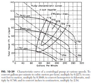
Note that the maximum pressure developed by the pump is determined from the pump characteristic curve at zero flow (or the minimum flow if there is a non-instrumented, passive spillback line that is not blocked off during the event). This maximum pressure is used to determine the credibility of some scenarios (for example, closed outlets) – if the centrifugal pump cannot generate enough pressure when completely blocked in to exceed the downstream maximum allowable working pressure (or equivalent), then overpressure does not occur.
The effect of a blocked outlet on a centrifugal pump should also be considered. For high speed, high head pumps, a blocked outlet may cause vibration, leading to reduced seal and bearing life. In severe cases, mechanical failure, such as catastrophic loss of the coupling, may occur. If there is a potential to valve-in both the inlet and discharge, then the pressure rise from mechanical heating of the liquid may cause overpressure. If the fluid is reactive, then blocking in one side may cause reactive issues due to the rapid temperature rise of the liquid. Ethylene oxide decomposition incidents involving blocked-in pumps are a common reference for this type of scenario.
Positive displacement compressors. For positive displacement (for example, reciprocating piston) compressors handling gases, some reduction in efficiency may occur at high compression ratios. This reduction in volumetric efficiency can be estimated using the techniques presented by the GPSA Engineering Data Book Section 13.2 Again, the impact of the event on the suction pressure should be accounted for.
Centrifugal compressors. For centrifugal compressors handling gases, an analysis like that for centrifugal pumps can be performed. Consideration should be given to avoiding compressor surge due to the decreased flow. If the compressor is not protected against surge, significant mechanical damage may occur.
Motors and turbines. The discussion above is based on constant speed drivers typical of electric motors. For alternative drivers, some consideration of the impact of the operation of the driver may be needed. Steam turbines may experience an overspeed prior to the overspeed trip.
To translate the pump characteristic curve at different speeds, the pump affinity laws are used. When translating the characteristic curve, it is important to remember to translate both the capacity and the head; that is, use the affinity laws for both the capacity and the head for each point on the curve. For example, using the excerpt from Perry’s given above, at a speed of 2,880 rpm, the pump can deliver approximately 66’ at 140 gpm. At a speed of 3,450 rpm, this data point translates to 66 × (3,450/2,880)2 ≈ 95’ at 140 × (3,450/2,880) ≈ 168 gpm.
Blog series information. This blog is part of a series on the proposed updates to the CCPS Guidelines 2nd edition §3.3 Venting Requirements for Nonreacting Cases that were removed during final editing. See the general CCPS Guidelines for Pressure Relief and Effluent Handling 2nd Edition review for more information.
[1] Boyce MP. Transport and Storage of Fluids – Head Meters. In Perry RH and Green DW. Perry’s Chemical Engineers’ Handbook. 1997; New York, McGraw Hill: 10.24-10.27.
[2] Gas Processors Suppliers Association Engineering Data Book, Twelfth Edition. 2004. Section 13: Compressors and Expanders.
We used Anthropic Claude [Opus 4.8] to assist with editing and converting a Microsoft Word manuscript into WordPress formatting.
0 Comments
Post a Comment